OUTLANDER 3G year 2012-2020
Twitter
Facebook
Snapchat
Instagram
Medium
REMOVAL AND INSTALLATION
Pre-removal Operation
Engine Upper Cover Removal (Refer to GROUP 13D - Fuel Injector
).
Battery and Battery Tray Removal (Refer to GROUP 54A - Battery
).
Post-installation Operation
Battery and Battery Tray Installation (Refer to GROUP 54A - Battery
).
Engine Upper Cover Installation (Refer to GROUP 13D - Fuel Injector
).
Removal steps
·
Harness bracket assembly (Refer to GROUP 13D - Common Rail
)
1.
Emission control equipment hose
2.
Glow wiring harness clamp
3.
Emission control equipment hose
4.
Vacuum pump pipe
5.
Control wiring harness clamp
6.
Vacuum hose connection
7.
Harness bracket
>>A<<
8.
Vacuum pump assembly
9.
O-ring
INSTALLATION SERVICE POINT
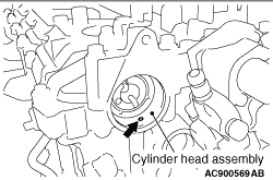
>>A<< VACUUM PUMP ASSEMBLY INSTALLATION
caution
Check whether foreign materials are not in the oil feed hole, shown in the illustration, of the cylinder head assembly.
Check whether foreign materials such as sealants are not on the inside surface of the vacuum pump installation hole. Install the vacuum pump assembly.
Menu
Homepage
Mitsubishi Cars
Outlander 2008
Outlander 2013
TRITON 2007
TRITON 2013
LANCER 2009
PAJERO 2009
PAJERO 2013
ASX 2013
i-MiEV 2011
Privacy Policy
About Us
Terms of Use
Contact Us
SERVICE MANUALS
TOYOTA
TOYOTA COROLLA
FORD
JEEP
Chevrolet
MAZDA CX-5
HYUNDAI
HONDA
Mercedes-Benz