|
|
Use M.U.T.-III to diagnose the CAN bus lines.
|
|
|
Q.
Is the check result normal?
|
|
|
 Repair the CAN bus line (Refer to GROUP 54C - Troubleshooting Repair the CAN bus line (Refer to GROUP 54C - Troubleshooting  ). ).
|
|
|
|
|
|
(1)Connect the negative battery terminal.
|
|
|
(2)After erasing the diagnosis code memory, check the diagnosis code again.
|
|
|
(3)Disconnect the negative battery terminal.
|
|
|
Q.
Is the diagnosis code No. B1433 set?
|
|
|
Intermittent malfunction (Refer to GROUP 00 - How to Use Troubleshooting/Inspection
Service Points - How to Cope with Intermittent Malfunction ).
|
|
|
|
|
|
(1)Check that the negative battery terminal is disconnected. If the negative battery
terminal is connected, disconnect it.
|
|
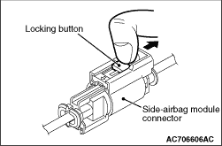
(2)Disconnect the left side-airbag module connector, unlock the connector by sliding the
locking button to the direction of the arrow as shown in the figure, and then disconnect the connector.
|
|
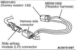
(3)Connect special tool dummy resistor (MB991865) to special tool resistor harness (MB991866).
(4)| caution |
Do not insert a probe directly into the terminal from the connector
front side as the connector contact pressure may be weakened.
|
Insert the resistor harness probe from the back of left side-airbag module harness side
connector.
(5)Connect the negative battery terminal.
(6)After erasing the diagnosis code memory, check the diagnosis code again.
(7)Disconnect the negative battery terminal.
Q.
Is the diagnosis code No. B1433 set?
 Go to Step 4. Go to Step 4.
Replace the front seatback pad and frame assembly (Refer to ).
|
|
|
(1)Check that the negative battery terminal is disconnected. If the negative battery
terminal is connected, disconnect it.
|
|
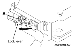
(2)While pushing the part "A" indicated in the figure of the harness side connector, turn
the lock lever to the direction of the arrow to release the lock lever, and disconnect the SRS-ECU
connector.
|
|
(3)| danger |
To release the connector short spring in the following operations,
disconnect this side-airbag module connector, and keep the squib circuit shorted.
|
Disconnect the left side-airbag module connector, unlock the connector by sliding the
locking button to the direction of the arrow as shown in the figure, and then disconnect the connector.
|
|
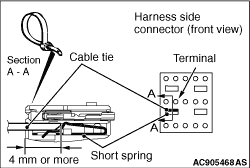
(4)| caution |
The short spring may not be released due to the insufficient insertion. Therefore, insert
the insulator for 4 mm or more.
|
Insert an insulator (width: 3 mm, thickness: 0.5 mm) such as cable tie between the SLS-,
SLS+ line and the short spring, and then release the short spring.
(5)Connect the negative battery terminal.
(6)Ignition switch: ON
(7)Take the measurements below at the SRS-ECU harness side connector.
- Voltage between SLS-, SLS+ line and body earth
OK: 1 V or less
(8)Disconnect the negative battery terminal.
Q.
Is the check result normal?
Go to Step 5.
Repair the wiring harness SLS-, SLS+ line between the SRS-ECU connector
and the left side-airbag module connector.
|
|
|
Q.
Is the diagnosis code No. B1433 set?
|
|
|
Replace SRS-ECU (Refer to ).
|
|
|
|
|
|
Intermittent malfunction (Refer to GROUP 00 - How to Use Troubleshooting/Inspection
Service Points - How to Cope with Intermittent Malfunction ).
|
|
|
|